
Description
’
-
Document No.: IM-P145-02 ST Issue1
-
Brand: Spirax Sarco
-
Copyright: Copyright 2005
-
Application: FTS14 series austenitic stainless steel float-operated steam traps, available in 1/2” (DN15), 3/4” (DN20), and 1” (DN25) sizes
1. Safety Information
Following these operating instructions and ensuring correct installation, commissioning, and maintenance by qualified personnel is the only guarantee of safe valve operation (see Section 11, Safety Information in the Appendix). During installation, strictly follow the piping layout, plant installation guidelines, and safety regulations. Use tools correctly and wear all necessary personal protective equipment.
1.1 Warnings
-
The cover gasket contains a sharp-edged stainless steel support ring. Improper handling or disposal may cause cuts.
-
If the fluoroelastomer “O” ring is used at temperatures of 315℃ (599F) or higher, it may decompose and produce hydrofluoric acid. Avoid skin contact with and inhalation of this acid, as it can cause skin burns and respiratory system damage.
1.2 Isolation Requirements
-
When closing isolation valves, consider the safety of other system components and personnel. Where necessary, provide ventilation, isolation equipment, protective devices, or alarm devices.
-
Close isolation valves gradually to prevent system shock caused by excessively rapid operation.
1.3 Pressure Control
-
Before maintenance, confirm that the valve has been completely isolated from the pressurized system and that pressure in the isolated section has been fully vented to atmosphere. Installation of a Spirax Sarco DV depressurization valve is recommended; refer to the applicable product documentation.
-
Never assume that pressure has been fully released solely because a pressure gauge reads “zero”. Confirm depressurization through a professional pressure-relief procedure.
1.4 Temperature Protection
- After isolation, allow the valve to cool to ambient temperature to prevent burns. Wear protective clothing and safety glasses during operation.
1.5 Waste Disposal
- The product is generally recyclable and will not harm the environment when disposed of correctly. Only the fluoroelastomer “O” ring requires special handling:
The waste may be landfilled in accordance with national or local environmental regulations.
-
The waste may be incinerated, provided a compliant scrubber is used to remove hydrogen fluoride produced during combustion.
-
The fluoroelastomer “O” ring is insoluble in aqueous solutions.
2. Product Overview
2.1 Main Function
FTS14 austenitic stainless steel float-operated steam traps include an automatic air vent. By efficiently discharging condensate and removing air, they help keep process equipment operating at optimum conditions.
2.2 Flow Direction and Installation Flexibility
-
Standard flow direction: Horizontal connection, with flow from right to left (R-L).
-
Flow direction adjustment: Remove the 4 cover bolts and rotate the cover to change the flow direction to horizontal left-to-right (L-R), vertical upward, or vertical downward. Replace the gasket during adjustment.
-
Note: For additional technical details, refer to Technical Information Sheet TI-P145-01.
2.3 Optional Additional Features
| Model | Main additional feature |
|---|---|
| FTS14X | Integral strainer protects internal components from damage caused by contaminants |
| FTS14-C | Integral steam-lock release device and thermostatic air vent for applications where steam locking may occur (see Section 3.11); the cover can be drilled and tapped with a 1/8” BSP thread for installing a PT100 or other temperature sensor, and is supplied with a stainless steel blanking plug |
2.4 Size and Pipe Connections
| Connection standard |
|---|
| Threaded connections: BS 21, DIN 2999 (metric), or NPT (ANSI B 1.20.1, US standard) |
| Socket-weld connections: 3799 Class 3000 or DIN 3239 |
| Flanged connections: DN15/20/25, complying with ANSI B 16.5 Class 150/300 or EN 1092-1/PN16/25 |
| Note: Consult Spirax Sarco for other connection types |
2.5 Limiting Conditions (ISO 6552)
| Parameter | Specification |
|---|---|
| Body design pressure | PN25 |
| Maximum allowable pressure (PMA) | 25 bar g (363 psi g) |
| Maximum allowable temperature (TMA) | 300℃ (572°F) |
| Maximum operating temperature (TM0) | 225℃ (437°F) |
| Minimum operating temperature | -20℃ (-4°F); consult the manufacturer for lower temperatures |
| Maximum cold hydraulic test pressure | 37.5 bar g (544 psi g) |
2.6 Operating Range
-
Pressure range: Refer to the operating range chart, which clearly identifies the “No use” area. Operation in this area may damage internal components.
-
Key information:
PM0: Maximum operating steam pressure.
-
Range A-B: Suitable for flanged connections (PN16/25, ANSI 300), threaded connections, and socket-weld connections.
-
Range A-C: Suitable for flanged connections (ANSI 150).
-
The maximum operating pressure and temperature for sanitary clamp connections are limited by the gasket or clamp specification used.
-
Maximum differential pressure (PMX):
| Model | Maximum differential pressure |
|---|---|
| FTS14 - 4.5 | 4.5 bar |
| FTS14 - 10 | 10 bar |
| FTS14 - 14 | 14 bar |
2.7 Materials Specification
| Component | Materials specification |
|---|---|
| Body and cover | Austenitic stainless steel (316), complying with EN 10213-4 (1.4408) and ASTM A351 CF8M |
| Cover bolts | Stainless steel, complying with BS EN 3506 A2-70 |
| Cover gasket | Reinforced exfoliated graphite |
| “O” ring | Nitrile rubber (FDA approved) |
| Internal components | Stainless steel |
3. Installation
Note: Before installation, carefully read Section 1, “Safety Information”. Refer to this guide, the product nameplate, and the technical manual to confirm that the product meets the installation requirements.
3.1 Preliminary Checks
-
Confirm that the product’s maximum pressure and temperature limits are compatible with the operating conditions of the installation. If the product limits are lower than the system conditions, install additional safety devices in the system to prevent overpressure.
-
Check that the installation location meets requirements and confirm that the flow direction matches the design.
-
Remove all plastic protective caps from the connections.
3.2 Discharge Safety
- If the steam trap discharges directly to atmosphere, ensure that the discharge point is in a safe location. Discharged liquid may reach 100℃ (212°F), creating a burn hazard.
3.3 Main Installation Requirements
-
Keep the float arm horizontal so that the float can move freely in the vertical direction. The side of the body marked “TOP” must be positioned uppermost for all installation flow directions.
-
Install the steam trap below the steam-system outlet and provide a length of descending pipe upstream of the trap. The standard length is 150mm/6”; see Figure 5. If a descending pipe cannot be installed, steam may flow above the condensate in the pipe under low-load conditions and enter the trap, causing steam locking.
3.4 Backpressure Management
- If backpressure exists in the condensate return line downstream of the trap, such as when the condensate line rises, install a check valve downstream of the trap. Spirax Sarco DCV41 is recommended; see Figure 4. This prevents waterlogging when inlet pressure falls or the steam line is shut off.
3.5 Bypass Installation Recommendation
- Bypass installation is not recommended: A bypass may leak, or the trap may be rendered ineffective if the bypass is inadvertently left open. This can waste steam and may increase pressure in the condensate return line.
3.6 Welding Requirements
- If the steam trap must be welded to the pipe, arc welding only is permitted, and the internal components do not need to be removed during welding. Other welding methods may deform the body or damage internal components.
3.7 Steam-Lock Prevention (Supplement to Section 3.11)
-
Installation location: Install the float-operated steam trap as close as possible to the outlet of the equipment requiring drainage. Minimize the pipe length between the condensate outlet and the trap to prevent the pipe from filling with steam and causing steam locking. Steam locking can cause waterlogging in the system and reduce equipment efficiency, similar to air locking in a water system.
-
High-risk applications: Rotary cylinders and other equipment that discharges condensate through a descending pipe or siphon pipe are susceptible to steam locking.
-
Solution: Install an automatic air vent and a steam-lock release valve (SLR). Proceed as follows:
Turn the SLR spindle counterclockwise to open the valve. The factory standard setting is 1/2 turn, corresponding to a bypass flow rate of 22kg/h@10 bar steam.
-
SLR flow adjustment: Turn the spindle counterclockwise to increase bypass flow and clockwise to reduce bypass flow.
-
Warning: Do not use the SLR for high-load steam blow-through, as this will shorten the service life of the steam trap. Consult Spirax Sarco when blow-through steam is required.
3.8 Protection in Exposed Environments
- If the steam trap is installed outdoors or in a low-temperature exposed environment, insulate the body or install a separate small thermostatic steam trap for drainage to prevent frost damage.
3.9 Maintenance Clearance
- Provide sufficient clearance during installation to allow the body to be removed later from the cover side. Required clearance:
DN15 (1/2”), DN20 (3/4”): 135mm (5.6”)
- DN25 (1”): 145mm
4. Commissioning
-
Before commissioning, confirm that the system has been completely installed and that alarm and protective devices, such as pressure-relief valves and check valves, have been tested and are operating correctly.
-
Follow the principle of “low pressure before high pressure, ambient temperature before elevated temperature”. Gradually verify that the steam trap discharges condensate and removes air correctly, with no leakage or steam locking.
5. Operation
5.1 Operating Principle
FTS14 is a continuous-discharge steam trap. Its operating sequence is as follows:
-
During system startup, the thermostatic air vent discharges air from the main valve to prevent air locking.
-
When hot condensate enters the trap chamber, the air vent closes. As the condensate level rises, the float rises and opens the main valve through the lever mechanism, discharging condensate.
-
When steam enters the trap chamber, the condensate level falls, lowering the float and closing the main valve to prevent steam leakage.
5.2 Operating Benefits
-
The trap handles high loads during startup, provides reliable sealing, and effectively protects against water hammer and system vibration.
-
If steam locking occurs during operation, replace the trap with a model equipped with an SLR, such as FTS14-C, and adjust the SLR according to Section 3.11.
6. Maintenance
Note: Before maintenance, carefully read Section 1, “Safety Information”. Confirm that the piping has been isolated, pressure has been fully released, and the body has cooled to ambient temperature.
6.1 General Maintenance Requirements
-
Isolate the piping before maintenance, safely discharge the pressurized medium to atmosphere, and wait for the body to cool before starting work.
-
During reassembly, ensure that all mating surfaces are clean. Replace damaged seals, including “O” rings and gaskets, and tighten bolts to the recommended torque; see Table 1.
-
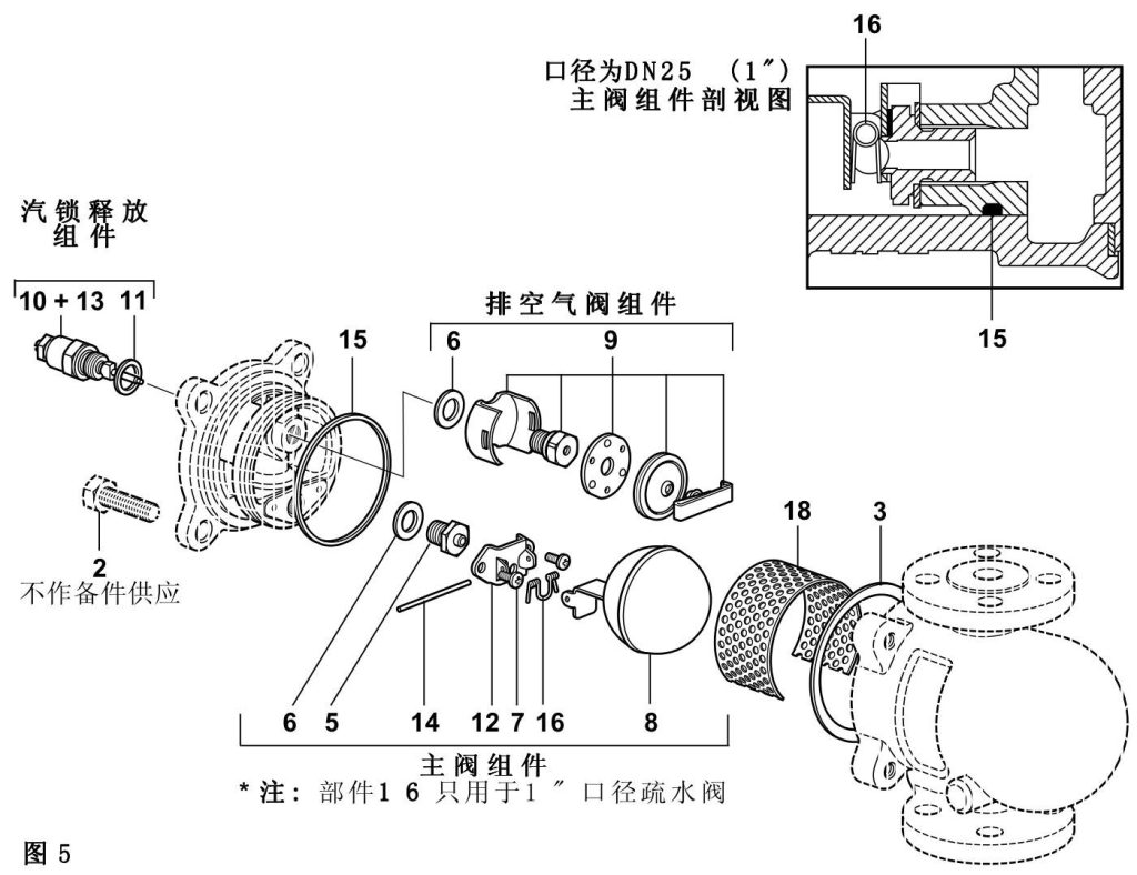
Perform maintenance with reference to Figure 5 on page 8, the main valve assembly sectional view.
6.2 Main Valve Assembly Procedure
-
Remove the cover bolts (item 2). Insert two screwdrivers into the gap between the body and cover, pry the body apart, and align the bolt holes.
-
Remove the pivot pin (item 14) and float assembly (item 8).
-
Remove the 2 main valve assembly screws (item 7) and pivot bracket (item 12).
-
Remove the main valve seat (item 5). Replace the main valve seat and matching gasket with new parts, then tighten to the recommended torque; see Table 1.
Note: Valve spring (item 16) is used only on DN25 (1”) steam traps.
-
Tighten the main valve assembly screws (item 7) to the recommended torque and install the pivot bracket (item 12). Reassemble the float assembly (item 8) and pivot pin (item 14).
-
Install a new “O” ring (item 15) on the body. Ensure that the contact surface is clean and undamaged. A suitable compliant lubricant may be applied to assist installation.
-
Install the cover with a new cover gasket (item 3), then tighten the cover bolts (item 2). Ensure that the “TOP” mark on the body is positioned uppermost for all installation flow directions.
6.3 Air Vent Assembly Procedure
-
Remove the spring clip, capsule, and baffle.
-
Unscrew the air vent seat (item 9) and gasket (item 6).
-
Install the new gasket, seat, and bracket, then tighten to the recommended torque; see Table 1.
-
Reinstall the baffle, capsule, and spring clip. Ensure that the air vent is positioned horizontally and that there is clearance between the bracket and cover.
6.4 Strainer Replacement (Installed Condition)
-
Remove the cover bolts (item 2) and pry the body apart using two screwdrivers.
-
Remove the strainer and clean it if reusable, or replace it with a new strainer.
-
When installing a new strainer, ensure that it is positioned between the 2 projections on both sides of the outlet end.
-
Reinstall the body with a new “O” ring (item 15) and cover gasket (item 3). Tighten the cover bolts to the recommended torque; see Table 1.
7. Spare Parts
7.1 Available Spare Parts
-
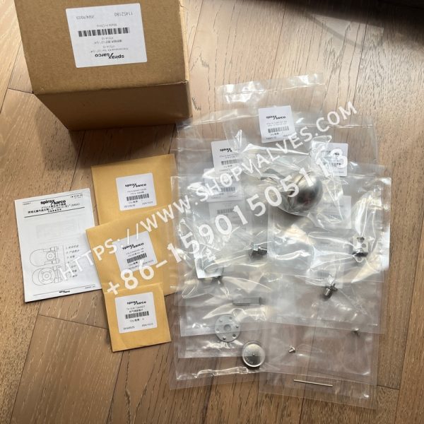
Maintenance kit: Includes item 6 (2 sets), item 7 (2 sets), item 8, item 9, item 12, item 14 (selected models only), and item 18.
-
Gasket set: Includes item 3 (3 pieces) and item 15.
-
Note: Spare parts are limited to components shown with solid lines in the manual illustrations. Components shown with dashed lines are not supplied as spare parts.
7.2 Spare Parts Ordering Requirements
-
Specify the following information when ordering: trap size, such as DN15/20/25; model, such as FTS14-X/C; and pressure range, such as 4.5/10/14 bar.
-
Ordering example: 1 maintenance kit for a Spirax Sarco 1/2” (DN15) FTS14-4.5 steam trap.