Description
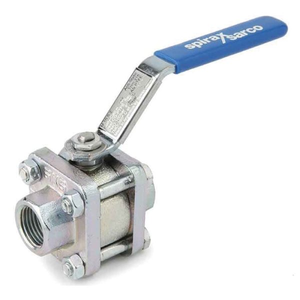
Spirax Sarco M10Si ISO ball valves (DN¼” to DN2½”) are three-piece ball valves intended for isolation service and must not be used as control valves. They are suitable for steam and other industrial fluids and can be used in environments ranging from vacuum to higher temperatures and pressures. The valves feature lockable full handles and allow in-line servicing without removal from the pipeline for threaded and welded versions only. Because the valve body does not need to be disassembled, integral ISO valve-body mounting enables valve automation without compromising seal integrity. Manual or remote control can be implemented safely and easily with these ball valves.
Available Models
| Model | Description |
|---|---|
| M10Si2__ISO | Zinc-plated carbon steel body, PDR 0.8 seats |
| M10Si3__ISO | Stainless steel body, PDR 0.8 seats |
| M10Si4__ISO | All stainless steel, PDR 0.8 seats |
Note: In the naming convention, FB indicates full bore and RB indicates reduced bore.
Standards and Certificates
-
Standard: Fully compliant with European Pressure Equipment Directive 97/23/EC; marking is available as required.
-
Certificate: EN 10204 3.1 certification is available.
Note: Specify the need for inspection certificates when ordering. Maximum working pressure may be limited by the flange standard; consult Spirax Sarco for details.
Sizes and Pipe Connections
Full Bore
| Size | Pipe connection | Applicable standard |
|---|---|---|
| 1/4”, 3/8”, 1/2”, 3/4”, 1”, 1-1/4”, 1-1/2”, 2” | Flanged | DN15 to DN50, ASME (ANSI) Class 150 |
| 1/4”, 3/8”, 1/2”, 3/4”, 1”, 1-1/4”, 1-1/2”, 2” | Threaded, welded (BSP,BSPT,API/NPT,BW,SW) | ASME (ANSI) Class 300, EN 1092 PN40 |
Reduced Bore
| Size | Pipe connection | Applicable standard |
|---|---|---|
| 1/4”, 3/8”, 1/2”, 3/4”, 1”, 1-1/4”, 1-1/2”, 2”, 2-1/2” | Flanged | DN15 to DN65, ASME (ANSI) Class 150 |
| 1/4”, 3/8”, 1/2”, 3/4”, 1”, 1-1/4”, 1-1/2”, 2”, 2-1/2” | Threaded, welded (BSP,BSPT,API/NPT,BW,SW) | ASME (ANSI) Class 300, EN 1092 PN40 |
Pressure and Temperature Limits
| Parameter | Description | Value |
|---|---|---|
| PMA | - | 100 bar g@60℃ |
| TMA | Maximum allowable temperature | 260 ℃ @0 bar g |
| TMA | Minimum allowable temperature | -29 ℃ |
| PMO | Maximum operating pressure with saturated steam | 17.5 bar g |
| TMO | Maximum operating temperature | 260 ℃ @0 bar g |
| TMO | Minimum operating temperature | -29 ℃ |
| - | Maximum design cold hydraulic test pressure | 150 bar g |
Note: Consult Spirax Sarco for service below -29℃. ΔPMX maximum differential pressure is limited by PMO. This product must not be used in prohibited areas identified on the pressure/temperature chart (A - B corresponds to 2”FB and 2½” RB; A - C corresponds to ¼” -1½” FB, RB and 2”RB).
Technical Data
| Technical parameter | Description |
|---|---|
| Flow characteristic | Modified linear |
| Bore | Full bore and reduced bore |
| Leakage rate | Test standard ISO 5208 (Class A)/EN12266-1 (Class A) |
| Anti-static | Complies with ISO 7121 and BS 5351 |
Materials
| No. | Component | Model | Material | Applicable standard/specification |
|---|---|---|---|---|
| 1 | Body | M10Si2 ISO | Zinc-plated carbon steel | ASTM A105 |
| 1 | Body | M10Si3 ISO | Stainless steel | ASTM A182 F 316L |
| 1 | Body | M10Si4 ISO | Stainless steel | - |
| 2 | Bonnet | M10Si2 ISO | Zinc-plated carbon steel | ASTM A105 |
| 2 | Bonnet | M10Si3 ISO | Stainless steel | ASTMA 182 F 316L |
| 2 | Bonnet | M10Si4 ISO | Stainless steel | - |
| 3 | Ball | - | Stainless steel | AISI 316 |
| 4 | Stem | - | Stainless steel | AISI 316 |
| 5 | Seat | - | Carbon/graphite-reinforced PTFE | PDR 0.8 |
| 6 | Stem seal | - | Anti-static reinforced PTFE | - |
| 7 | Separator | M10Si2 ISO | Zinc-plated carbon steel | SAE 1010 |
| 7 | Separator | M10Si3 ISO | Stainless steel | AISI 316 |
| 7 | Separator | M10Si4 ISO | Stainless steel | - |
| 8 | Belleville washer | - | Stainless steel | AISI 301 |
| 9 | Nut | M10Si2 ISO | Zinc-plated carbon steel | SAE 1010 |
| 9 | Nut | M10Si3 ISO | Stainless steel | AISI 304 |
| 9 | Nut | M10Si4 ISO | Stainless steel | - |
| 10 | Nameplate (unmarked) | - | Stainless steel | AISI 430 |
| 11 | Stem nut | M10Si2 ISO | Zinc-plated carbon steel | - |
| 11 | Stem nut | M10Si3 ISO | Stainless steel | SAE 1010 |
| 11 | Stem nut | M10Si4 ISO | Stainless steel | AISI 304 |
| 12 | Link | M10Si2 ISO | Zinc-plated carbon steel | SAE 1010 |
| 12 | Link | M10Si3 ISO | Stainless steel | - |
| 12 | Link | M10Si4 ISO | Stainless steel | AISI 316 |
| 14 | Handle | - | Vinyl | - |
| 15 | Bolt | M10Si2 ISO | Zinc-plated carbon steel | Grade 5 |
| 15 | Bolt | M10Si3 ISO | Stainless steel | - |
| 15 | Bolt | M10Si4 ISO | Stainless steel | AISI 304 |
| 16 | Nut | M10Si2 ISO | Zinc-plated carbon steel | - |
| 16 | Nut | M10Si3 ISO | Stainless steel | SAE 1010 |
| 16 | Nut | M10Si4 ISO | Stainless steel | AISI 304 |
| 17 | Stud bolt | M10Si4 ISO | Stainless steel | AISI 316 |
| 18 | Retaining pin | M10Si2 ISO | Zinc-plated carbon steel | SAE 12L 14 |
| 18 | Retaining pin | M10Si3 ISO | Stainless steel | - |
| 18 | Retaining pin | M10Si4 ISO | Stainless steel | AISI 304 |
| 19 | Body/bonnet gasket | - | O-ring (EPDM) | - |
| 20 | Locknut | - | Stainless steel | AISI 316 |
| 21 | Lockable handle | M10Si2 ISO | Zinc-plated carbon steel | SAE 1010 |
| 21 | Lockable handle | M10Si3 ISO | Stainless steel | - |
| 21 | Lockable handle | M10Si4 ISO | Stainless steel | AISI 316 |
| 22 | Stem seal | - | PEEK | - |
| 23 | Locking plate | - | Stainless steel | AISI 304L |
Approximate Weight kg
| Size | Reduced bore | Reduced bore | Reduced bore | Reduced bore | Full bore | Full bore | Full bore | Full bore |
|---|---|---|---|---|---|---|---|---|
| - | Threaded/butt-weld/socket-weld | PN40 | ASME 150 | ASME 300 | Threaded/butt-weld/socket-weld | PN40 | ASME 150 | ASME 300 |
| ¼” | 0.65 | - | - | - | 0.65 | - | - | - |
| 3/8” | 0.65 | - | - | - | 0.72 | - | - | - |
| ½” | 0.72 | 2.30 | 1.77 | 1.70 | 0.95 | 2.60 | 1.87 | 2.40 |
| ¾” | 0.95 | 3.20 | 2.35 | 2.28 | 1.60 | 3.80 | 2.73 | 3.79 |
| 1” | 1.60 | 4.20 | 3.47 | 2.91 | 2.05 | 4.70 | 3.55 | 5.01 |
| 1¼” | 2.05 | 5.70 | 4.47 | 4.15 | 2.75 | 6.40 | 4.76 | 6.50 |
| 1½” | 2.75 | 6.80 | 5.96 | 5.88 | 4.25 | 8.30 | 5.82 | 9.22 |
| 2” | 4.25 | 9.50 | 9.16 | 8.12 | 7.50 | 12.80 | 11.91 | 13.99 |
| 2½” | 7.50 | - | - | 15.85 | - | - | - | - |
KV Values
| Size | Reduced bore KV value | Full bore KV value |
|---|---|---|
| ¼” | 2.5 | 2.5 |
| 3/8” | 6.8 | 6.8 |
| ½” | 6 | 17 |
| ¾” | 10 | 36 |
| 1” | 27 | 58 |
| 1¼” | 49 | 89 |
| 1½” | 70 | 153 |
| 2” | 103 | 205 |
| 2½” | 168 | - |
Conversion formulas: (C_{v}(UK)=K_{v} ×0.963); (C_{V}(US)=K_{V} ×1.156)
Operating Torque (Nm)
| Size | Reduced bore torque | Full bore torque |
|---|---|---|
| ¼” | 3.25 | 3.25 |
| 3/8” | 3.25 | 3.25 |
| ½” | 3.25 | 5.50 |
| ¾” | 5.50 | 13.25 |
| 1” | 13.25 | 20 |
| 1¼” | 20 | 50 |
| 1½” | 50 | 60 |
| 2” | 60 | 75 |
| 2½” | 75 | - |
The torque values above apply to frequently operated valves at a maximum differential pressure of 40 bar. For valves remaining in a fixed position for extended periods, torque may increase slightly.
Maintenance
Refer to the installation and maintenance guide supplied with the product for detailed information.
Ordering
-
Ordering example: Spirax Sarco ½” threaded M10Si2FB ISO ball valve.
-
Ordering information: If the model has not been selected before ordering, provide the service parameters, including nominal size and fluid properties such as nominal pressure/temperature, viscosity, or acidity/alkalinity, as well as body and ball materials. If the model has already been selected, order directly by model. For critical applications or complex piping systems, providing design drawings and detailed parameters is recommended for professional review.
Options
-
Self-venting ball
-
Extended stem (50mm/2” and 100mm/4”) for complete insulation
-
Oval handle for confined spaces, especially steam trap stations
Spare Parts
-
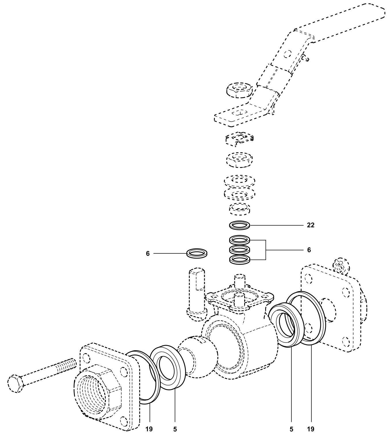
Available spare parts: Seat, stem, and body sealing kits (corresponding to component numbers 5, 6, 19, and 22)
-
Spare parts information: Spare parts are indicated by solid lines; parts indicated by dashed lines are not supplied as spare parts.
-
Ordering spare parts: Order by the available spare-part type listed above and specify the valve size and model.
-
Spare-parts ordering example: Seat and stem sealing kit for a ½” M10Si2FB ISO ball valve.
Installation Precautions
-
Pre-installation inspection: Carefully inspect the body, ball, stem, and other components for completeness and damage. Check that seals are not loose or damaged to prevent gas or liquid leakage.
-
Installation location: Select a location that is easy to operate and facilitates opening, closing, and maintenance. Also consider the flow path when the valve is open to avoid unnecessary pressure loss.
-
Piping requirements: Upstream and downstream piping should be coaxial, and the two flange sealing faces should be parallel. The piping must be capable of supporting the ball valve weight; otherwise, provide suitable supports. Blow through the piping upstream and downstream of the valve to remove oil, welding slag, and other contaminants.
-
Valve inspection: Verify the ball valve markings and confirm that the valve is undamaged. Fully open and close the valve several times to confirm proper operation. Remove the protective components from the connecting flanges at both ends, then inspect and clean the valve bore; even small particles between the seat and ball can damage the seat sealing surface.
-
Installation details: Either end of the ball valve may be installed on the upstream side. Handle-operated ball valves may be installed in any pipeline position. Ball valves with gearboxes or pneumatic actuators should be installed vertically, with the actuator above horizontal piping. Install gaskets between the valve and pipeline flanges as required by the piping design. Tighten flange bolts symmetrically, progressively, and evenly. When using a pneumatic actuator, connect the pneumatic tubing.
-
Special welding requirements: Before welding socket-weld and butt-weld valves, remove the end caps from the body and remove the R-PTFE seats. Weld the end caps to the pipeline, then reinstall the R-PTFE seats and reassemble the valve. Before disassembly and commissioning, confirm that no medium is flowing through the pipeline.
-
Steam system requirements: When used in steam systems, install a steam trap upstream of the valve. Open the valve slowly to prevent water hammer.
Seal Integrity Check
After closing the ball valve, assess sealing by observing the stem position. If the stem is fully retracted, the seal is satisfactory. If the stem protrudes, leakage may be present and should be addressed promptly.
Operating Precautions
-
Operating pressure: Pressure must comply with the product specifications. Excessively high or low pressure may affect normal operation.
-
Temperature range: Materials and sealing performance must match the fluid temperature range. Excessively high or low temperatures may cause damage or prevent operation.
-
Opening and closing: Open and close the valve slowly to avoid severe vibration. Monitor changes in valve flow to ensure stable fluid control.