
Description
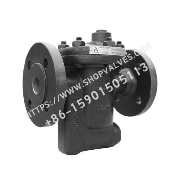
Inverted Bucket Steam Trap – 990F Series
900F Series cast steel inverted bucket steam traps feature integral horizontal pipe connections and a vertical integral strainer. Connection options include threaded, socket weld, and flanged connections.
900F Series features a unique lever system that multiplies the force generated by the inverted bucket, enabling it to open the valve against system pressure. The mechanism is free-floating, with no fixed pivot points that could cause wear or friction. Because the mechanism is installed at the top of the trap, dirt does not accumulate at the valve orifice. Small dirt particles remain suspended until the bucket sinks and pulls the valve disc away from the seat, allowing the pressure differential to discharge the particles. The discharge orifice is surrounded by a water seal to prevent the loss of live steam.
A small vent hole in the bucket creates an automatic air-venting system that continuously discharges air and CO2 at steam temperature.
Although condensate discharge may occasionally be interrupted, inverted bucket traps provide continuous drainage and prevent condensate backup. The valve is also resistant to water hammer.
Product Specifications
| Model | 991F | 992F | 993F | 994F | 995F | 996F |
|---|---|---|---|---|---|---|
| Capacity | 9072 kg/hr (20000 lb/hr) | 9072 kg/hr (20000 lb/hr) | 9072 kg/hr (20000 lb/hr) | 9072 kg/hr (20000 lb/hr) | 9072 kg/hr (20000 lb/hr) | 9072 kg/hr (20000 lb/hr) |
| Maximum allowable pressure | 37 barg @ 343 °C (493 psig @ 650 °F) | 37 barg @ 343 °C (493 psig @ 650 °F) | 37 barg @ 343 °C (493 psig @ 650 °F) | 37 barg @ 343 °C (493 psig @ 650 °F) | 37 barg @ 343 °C (493 psig @ 650 °F) | 37 barg @ 343 °C (493 psig @ 650 °F) |
| Body material | ASTM A216 WCB carbon steel | ASTM A216 WCB carbon steel | ASTM A216 WCB carbon steel | ASTM A216 WCB carbon steel | ASTM A216 WCB carbon steel | ASTM A216 WCB carbon steel |
| Maximum operating pressure | 28 barg (400 psig) | 17 barg (250 psig) | 31 barg (500 psig) | 26 barg (375 psig) | 34 barg (500 psig) | 34 barg (500 psig) |
| Connection type | Integral flanges | Integral flanges | Integral flanges | Integral flanges | Integral flanges | Integral flanges |
| Nominal size | 20 mm (3/4″) 25 mm (1″) | 20 mm (3/4″) 25 mm (1″) | 20 mm (3/4″) 25 mm (1″) 32 mm (1-1/4″) | 25 mm (1″) 32 mm (1-1/4″) | 40 mm (1-1/2″) 50 mm (2″) | 40 mm (1-1/2″) 50 mm (2″) |
| Flow direction | Horizontal | Horizontal | Horizontal | Horizontal | Horizontal | Horizontal |