Description
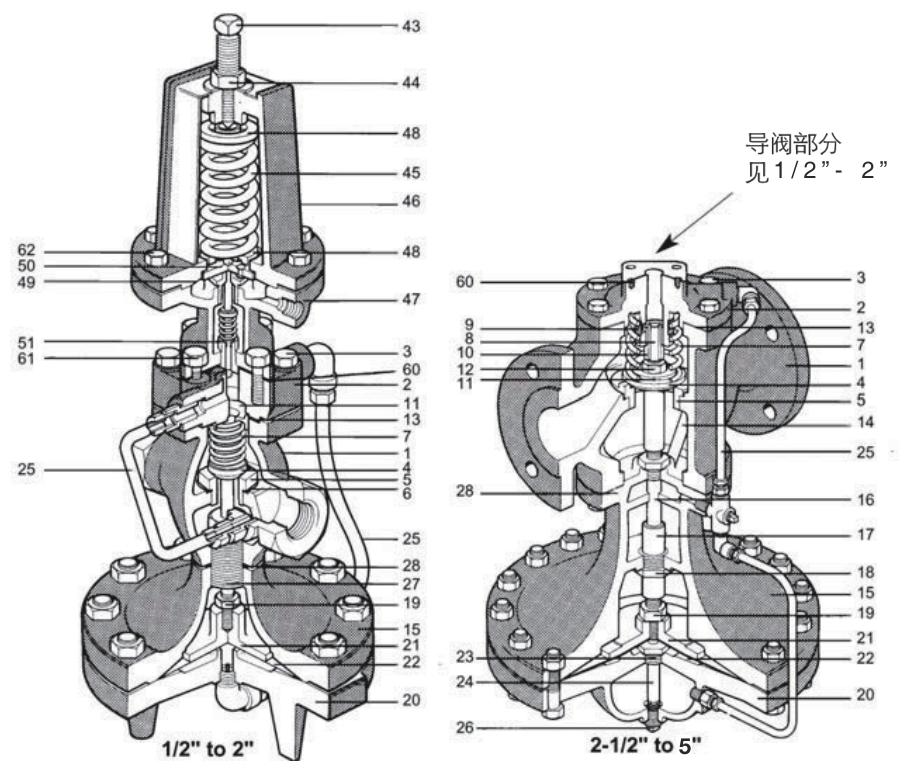
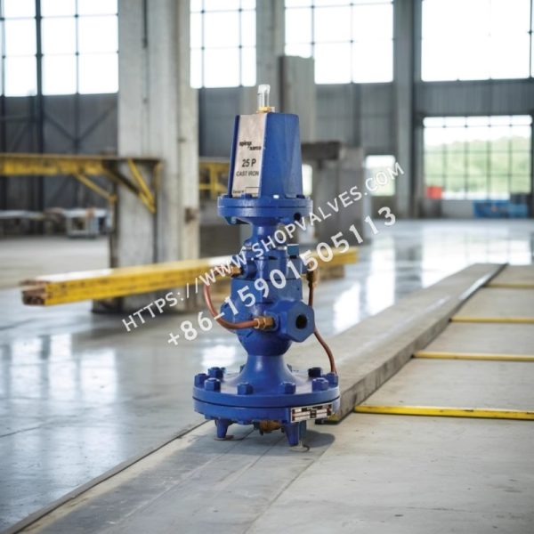
Spirax Sarco 25P pilot-operated pressure-reducing valve, ½” - 5”, is a self-acting pilot-operated pressure-reducing valve. An external pressure-sensing line detects downstream pressure, adjusts the main valve opening, and maintains stable pressure. The valve can close when there is no downstream demand. The main valve features a single seat and a hardened alloy valve plug. The valve body is made of ductile iron or cast steel, and the pilot valve is bolted directly to the main valve.
Available Models
| Model | SKU |
|---|---|
| 1/2” 25P SG Blue | 6090328 |
| 3/4” 25P SG Blue | 6090331 |
| 1” 25P SG Blue | 6090334 |
| 1 1/4” 25P SG Blue | 6090337 |
| 1 1/2” 25P SG Blue | 6090340 |
| 2” 25P SG Blue | 6090343 |
Downstream Pressure Range
-
Yellow spring: 0.2 bar g - 2.1 bar g
-
Blue spring: 1.4 bar g - 7.0 bar g
-
Red spring: 5.6 bar g - 14.0 bar g
Size and Pipe Connections
-
½” - 2”: BSPT threaded connection (BS21)
-
½” - 4”: PN16 and PN25 flanges (ductile iron), PN40 flanges (cast steel)
-
5”: PN16 and PN25 flanges (ductile iron)
-
Contact Spirax Sarco for other connection sizes.
Weight
| Size | Weight (cast iron) (kg) |
|---|---|
| 1/2” | 10.8 (threaded), 11.4 (flanged) |
| 3/4” | 10.2 (threaded), 12.2 (flanged) |
| 1” | 13.6 (threaded), 16 (flanged) |
| 1 1/4” | 16 (threaded), 18.8 (flanged) |
| 1 1/2” | 15.8 (threaded), 20.4 (flanged) |
| 2” | 26 (threaded), 31.2 (flanged) |
| 2 1/2” | 62.4 (flanged) |
| 3” | 74.6 (flanged) |
| 4” | 112.2 (flanged) |
| 5” | 132 (flanged) |
Materials
| No. | Component | Material |
|---|---|---|
| 1 | Valve body | Ductile iron QT400 - 18 |
| 2 | Bonnet | Ductile iron QT400 - 18 |
| 3 | Bonnet bolts | Steel SAEJ429 Grs |
| 4 | Main valve plug | Stainless steel AISI 420 |
| 5 | Main valve seat (1/2” - 2”) | Stainless steel AISI 420 |
| 5 | Main valve seat (2 1/2” - 5”) | Stainless steel AISI 304 |
| 6 | Main valve seat gasket | Copper |
| 7 | Valve return spring | Stainless steel AISI 302 |
| 8 | Strainer screen | Stainless steel AISI 304 |
| 9 | Valve stem | Stainless steel AISI 304 |
| 10 | Valve stem sleeve (1/2” - 2”) | Brass |
| 10 | Valve stem sleeve (2 1/2” - 5”) | Steel |
| 11 | Bonnet gasket | Asbestos-free material |
| 12 | Spring guide | Steel SAEJ995 |
| 13 | Nut (1/2” - 2”) | Brass |
| 13 | Nut (2 1/2” - 5”) | Steel |
| 14 | Pressure-balancing tube | Stainless steel AISI 304 |
| 15 | Diaphragm top cover | Ductile iron QT400 - 18 |
| 16 | Valve stem bushing | Stainless steel AISI 304 |
| 17 | Diaphragm bottom cover (1/2” - 2”) | Brass |
| 17 | Diaphragm bottom cover (2 1/2” - 5”) | Cast iron |
| 18 | Pushrod guide (1/2” - 2”) | Brass |
| 18 | Pushrod guide (2 1/2” - 5”) | Stainless steel |
| 19 | Diaphragm plate | Ductile iron QT400 - 18 |
| 20 | Diaphragm plate pushrod | Stainless steel AISI 304 |
| 21 | Nut (2 1/2” - 5”) | Steel |
| 22 | Main diaphragm (1/2” - 3”) | Phosphor bronze |
| 22 | Main diaphragm (4” - 5”) | Stainless steel |
| 23 | Sleeve | Stainless steel AISI 304 |
| 24 | Short tube and damping orifice | 12L14 |
| 25 | External tubing assembly | Stainless steel ASTM B280 |
| 26 | Plug | Steel 12L14 |
| 27 | Connecting bolts | Steel SAE1060 |
| 28 | Adjusting screw (1/2” - 2”) | Brass |
| 28 | Adjusting screw (2 1/2” - 5”) | Stainless steel |
| 43 | Pilot valve spring | Copper, asbestos-free |
| 44 | Locknut | Steel |
| 45 | Washer | Stainless steel AISI 304 |
| 46 | Diaphragm top cover | Ductile iron QT400 - 18 |
| 47 | Spring plate | Stainless steel ASTM B283 |
| 48 | Diaphragm bottom cover | Brass SAE1010 |
| 49 | Pilot valve spring | Steel SAE1010 |
| 50 | Diaphragm plate | Ductile iron QT400 - 18 |
| 51 | Diaphragm | Phosphor bronze AISI 302 |
| 60 | Pilot valve gasket | Graphite/asbestos AISI 302 |
| 61 | Pilot valve mounting nut | Steel SAE J 429 Grs |
| 62 | Diaphragm chamber nut | Steel / 1 - 18x1” SAE J429 Grs |
Installation
Install the pressure-reducing valve in a horizontal pipeline with a bypass and isolation valves. Install a steam trap and strainer upstream of the valve. Provide a straight pipe section of at least 10 pipe diameters upstream and downstream of the downstream pressure-sensing line.
Flow Capacity
| Size | Cv |
|---|---|
| 1/2” | 3.4 |
| 3/4” | 6.5 |
| 1” | 10.5 |
| 1 1/4” | 14 |
| 1 1/2” | 20 |
| 2” | 35 |
| 2 1/2” | 56 |
| 3” | 74 |
| 4” | 115 |
| 5” | 123 |
Typical Applications
25P provides accurate and reliable pressure reduction, reducing steam from high pressure to the equipment’s effective operating range and helping prevent equipment damage.