Description
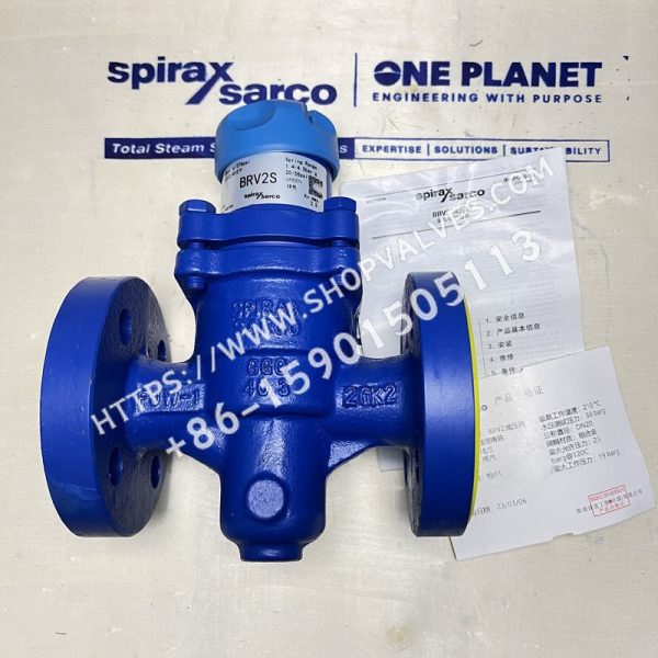
Spirax Sarco BRV2S and BRV2B ductile iron pressure reducing valves are direct-acting pressure reducing valves suitable for steam or gases such as compressed air. The valves feature ductile iron bodies and are available with flanged or threaded connections. BRV2S has a stainless steel bellows, while BRV2B has a phosphor bronze bellows. BRV2SP and BRV2BP models with an optional external sensing pipe are also available. Three downstream pressure ranges are available and are identified by the color of the designation plate.
Available Models
| Model | SKU |
|---|---|
| DN15 BRV2S GREY (0.14 - 1.7 bar g) | 0457393 |
| DN15 BRV2S GREEN (1.40 - 4.0 bar) | 0457493 |
| DN15 BRV2S ORG (3.50 - 8.6 bar g) | 0457593 |
| DN20 BRV2S GREY (0.14 - 1.7 bar g) | 0458393 |
| DN20 BRV2S GREEN (1.40 - 4.0 bar) | 0458493 |
| DN20 BRV2S ORG (3.50 - 8.6 bar g) | 0458593 |
| DN25 BRV2S GREY (0.14 - 1.7 bar g) | 0459393 |
| DN25 BRV2S GREEN (1.40 - 4.0 bar) | 0459493 |
| DN25 BRV2S ORG (3.50 - 8.6 bar g) | 0459593 |
Downstream Control Pressure Ranges
| Color | Pressure Range |
|---|---|
| Grey | 0.14 - 1.7 bar g |
| Green | 1.40 - 4.0 bar g |
| Orange | 3.50 - 8.6 bar g |
Note: Where pressure ranges overlap, the lower-range spring provides better control. The product fully complies with the European Pressure Equipment Directive 97 / 23 / EC and is supplied with CE marking where required. Standard products are supplied with the manufacturer’s typical test certificate. Specify any required certificates and test requirements when ordering.
Sizes and Pipe Connections
-
½”, ¾” and 1”: threaded connections BSP (BS 21 Rp) or NPT
-
DN15, DN20 and DN25: flanges EN 1092 PN25
Pressure/Temperature Limits
| Item | Parameter |
|---|---|
| Valve body design conditions | PN25 |
| PMA maximum allowable pressure | 25 bar g @ 120 °C |
| TMA maximum allowable temperature | 210 °C @ 19 bar g |
| Minimum allowable temperature | -10 °C |
| PMO maximum operating pressure for saturated steam | 19 bar g @ 210 °C |
| TMO maximum operating temperature | 210 °C @ 19 bar g |
| Minimum operating temperature | 0 °C (consult Spirax Sarco below this temperature) |
| Maximum downstream set pressure | 8.6 bar g |
| Maximum differential pressure | 19 bar |
| Recommended maximum pressure reduction ratio (at maximum flow) | 10 : 1 |
| Design maximum cold hydraulic test pressure | 38 bar g (after internal components are installed, the test pressure must not exceed 19 bar g) |
Materials
| Item No. | Component | Material |
|---|---|---|
| 1 | Spring housing | Aluminum - epoxy-coated LM24 |
| 2 | Adjusting handwheel | Polypropylene |
| 3 | Upper spring plate | Cast iron DIN 1691 GG 20 |
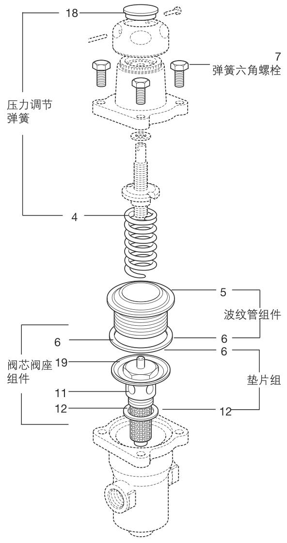
| 4 | Pressure adjustment spring | Silicon chrome BS 2803 685 A55, spring steel, stainless steel 316T/316L |
| 6 | Bellows assembly gasket | Stainless steel-reinforced exfoliated graphite |
| 7 | Spring housing bolt (M8 × 25mm) | Zinc-plated steel BS 3692 Gr. 8.8 |
| 8 | Valve body | Ductile iron DIN 1693 GGG 40.3 |
| 9 | Taper washer | Stainless steel ASTM A276 316L |
| 10 | Top stem | Stainless steel ASTM A276 316L |
| 11 | Valve seat | Stainless steel BS 970 431 S29 |
| 12 | Valve seat gasket | Stainless steel BS 1449 316 S11 |
| 13 | Valve plug | Stainless steel AISI 420 |
| 14 | Valve plug return spring | Stainless steel BS 20056 316 S42 |
| 15 | Strainer screen | Stainless steel BS 1449 316 SH |
| 16 | Plug | Stainless steel BS 970 431 S29 |
| 17 | Compression fitting assembly | Brass |
| 18 | Spring range color designation plate | Polypropylene |
| 19 | Partition plate | Stainless steel 316L |
| 20 | Pin | Copper-plated low-carbon steel |
Note: Items 10, 11, 13, 14, 15 and 19 are components of a single assembly.
Flow Data for Safety Valve Sizing
Use the full-open flow rate for safety valve sizing. Kvs values are: 1.5 for DN15, 2.5 for DN20 and 3.0 for DN25.
Conversion formulas:
-
Cv (US) = Kv x 1.156
-
Cv (UK) = Kv x 0.963
Weights
| Size | Threaded Connection Weight (kg) | Flanged Connection Weight (kg) |
|---|---|---|
| DN15 - ½” | 1.60 | 3.90 |
| DN20 - ¾” | 1.70 | 4.25 |
| DN25 - 1” | 1.95 | 4.65 |
Installation Instructions
Install the pressure reducing valve in a horizontal pipeline, following the flow direction indicated by the arrow on the valve body. For BRV2SP/BRV2BP models using an external sensing pipe, remove plug (16) and install the 6mm O/D compression fitting (17). The other end of the 6mm sensing pipe should be connected to the pipe at least 1m downstream of the valve.
Ordering Information
Order according to the descriptions in the available spare parts list, specifying the pressure reducing valve size, model and pressure range. Example: adjustment spring for a DN15 BRV2 pressure reducing valve, pressure range 3.5 - 8.6 bar g (orange); 1 - DN15 BRV2S pressure reducing valve, ductile iron body, flanged connection EN1092 PN25, stainless steel bellows, fitted with orange spring (3.5 - 8.6 bar g).
For detailed safety information and installation and maintenance instructions, see the Installation and Maintenance Instructions (IM-P045-10) supplied with the product.