
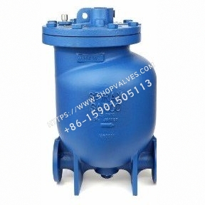
Description
Spirax Sarco MFP14, MFP14S and MFP14SS automatic pumps use steam or compressed air as the motive power to lift condensate and other liquids to elevated levels. Where suitable, they can drain equipment operating under vacuum or pressure. Combined with float-operated steam traps, they effectively remove condensate from temperature-controlled heat exchangers under a wide range of operating conditions.
Available Models
| Body Material | Model |
|---|---|
| Ductile iron | MFP14 |
| Cast steel | MFP14S |
| Stainless steel | MFP14SS |
Standards and Certificates
The products comply with the European Pressure Equipment Directive 97/23/EC and ATEX Directive 94/9/EC. EN 10204 3.1 certificates are available. The design complies with AD-Merkblatter and ASME VIII Div 1 standards. Specify the required certificates when ordering.
Sizes and Pipe Connections
| Model | Size and Connection Type |
|---|---|
| MFP14 | 1”, 1½”, 2” and 3” x 2” BSP threaded connections (BS 21 parallel); DN25, DN40, DN50 and DN80 x DN50 flanged connections to EN 1092 PN16, ANSI B 16.5 Class 150 and JIS/KS B 2238 10 |
| MFP14S | DN50 flanged connections to EN 1092 PN16, ANSI B 16.5 Class 150 and JIS/KS B2238 10; 2” BSP/NPT threaded connections available for special requirements |
| MFP14SS | DN50 flanged connections to EN 1092 PN16, ANSI B 16.5 Class 150 and JIS/KS B 2238 10; 2” BSP/NPT threaded connections available for special requirements |
| Steam or compressed air inlet | ½” BSP/NPT |
| Exhaust outlet | 1” BSP/NPT |
Additional Options
-
Electronic monitor: A ½” BSP threaded connection is provided at the top of the pump cover for connection to an electronic monitor, such as EPM1, which features a simple 8-digit LCD display and an integral 1.5-volt lithium battery, or EPM2, which can be connected to a remote counter or building energy management system (BEMS).
-
Insulation cover: Custom-made for each MFP14 size, the insulation cover provides both safety and energy-saving benefits. See TI-P136-07 for details.
Materials
| No. | Component | Material | MFP14 | Material | MFP14S | Material | MFP14SS |
|---|---|---|---|---|---|---|---|
| 1 | Pump cover | Ductile iron | EN JS 1025, EN-GJS-400-18-LT | Cast steel | DIN GSC 25N, ASTM A216 WCB | Stainless steel | BS EN 10213-4, 144091, ASTM A351 CF3M |
| 2 | Pump cover gasket | - | - | - | - | - | - |
| 3 | Pump cover bolt | Stainless steel | ISO 3506 Gr. A2-70 | Stainless steel | ISO 3506 Gr. A2-70 | Stainless steel | ISO 3506 Gr. A2-70 |
| 4 | Pump body | Ductile iron | EN-GJS-400-18-LT | Cast steel | DIN GSC 25N, ASTM A216 WCB | Stainless steel | BS EN 10213-4, 144091, ASTM A351 CF3M |
| 5 | Pillar | Stainless steel | BS 970, 431 S29 | Stainless steel | BS 970, 431 S29 | Stainless steel | BS 970, 431 S29 |
| 6 | Connecting rod, float and rod | Stainless steel | BS 1449, 304 S11 | Stainless steel | BS 1449, 304 S11 | Stainless steel | BS 1449, 304 S11 |
| 7 | Float | Stainless steel | AISI 304 | Stainless steel | AISI 304 | Stainless steel | AISI 304 |
| 8 | Lifting eye, integral | Ductile iron | EN-GJS-400-18-LT | Cast steel | DIN GSC 25N, ASTM A216 WCB | Stainless steel | BS EN 10213-4, 144091, ASTM A351 CF3M |
| 9 | Mechanism linkage | Stainless steel | BS 3146 pt.2 ANC 2 | Stainless steel | BS 3146 pt.2 ANC 2 | Stainless steel | BS 3146 pt.2 ANC 2 |
| 10 | Spring | Inconel 718 | ASTM 5962/ASTM B367 | Inconel 718 | ASTM 5962/ASTM B367 | Inconel 718 | ASTM 5962/ASTM B367 |
| 11 | Plug | Steel | DIN 267 Part III Class 5.8 | Steel | DIN 267 Part III Class 5.8 | Steel | DIN 267 Part III Class 5.8 |
| 12 | Check valve | Stainless steel | - | Stainless steel | - | Stainless steel | - |
| 13 | Screwed flange | Steel | - | Steel | - | Steel | - |
| 14 | Mechanism bracket | Stainless steel | BS 3146 pt. 2 ANC 4B | Stainless steel | BS 3146 pt. 2 ANC 4B | Stainless steel | BS 3146 pt. 2 ANC 4B |
| 15 | Bracket bolt | Stainless steel | BS 6105 Gr. A2-70 | Stainless steel | BS 6105 Gr. A2-70 | Stainless steel | BS 6105 Gr. A2-70 |
| 16 | Inlet valve seat | Stainless steel | BS 970, 431 S29 | Stainless steel | BS 970, 431 S29 | Stainless steel | BS 970, 431 S29 |
| 17 | Inlet valve | Stainless steel | ASTM A276 440B | Stainless steel | ASTM A276 440B | Stainless steel | ASTM A276 440B |
| 18 | Inlet valve seat gasket | Stainless steel | BS 1449 409 S19 | Stainless steel | BS 1449 409 S19 | Stainless steel | BS 1449 409 S19 |
| 19 | Exhaust valve seat | Stainless steel | BS 970 431 S29 | Stainless steel | BS 970 431 S29 | Stainless steel | BS 970 431 S29 |
| 20 | Exhaust valve | Stainless steel | BS 3146 pt. 2 ANC 2 | Stainless steel | BS 3146 pt. 2 ANC 2 | Stainless steel | BS 3146 pt. 2 ANC 2 |
| 21 | Exhaust valve seat gasket | Stainless steel | BS 1449 409 S19 | Stainless steel | BS 1449 409 S19 | Stainless steel | BS 1449 409 S19 |
| 22 | EPM actuator | Alnico | - | Alnico | - | Alnico | - |
| 23 | O-ring seal | EPDM | - | EPDM | - | EPDM | - |
| 28 | Spring retaining pin | Stainless steel | BS 970 431 S29 | Stainless steel | BS 970 431 S29 | Stainless steel | BS 970 431 S29 |
Pressure/Temperature Limits
| Body Design Condition | MFP14 | MFP14S | MFP14SS |
|---|---|---|---|
| Maximum motive fluid inlet pressure, steam or other gas | 13.8 bar g | 13.8 bar g | 10.96 bar g |
| PMA maximum allowable pressure | 16 bar g@120°C | 16 bar g@120°C | 16 bar g@93°C |
| TMA maximum allowable temperature | 300°C@12.8 bar g | 300°C@10.8 bar g | 300°C@9.3 bar g |
| Minimum allowable temperature; consult Spirax Sarco for low-temperature applications | 0°C | 0°C | 0°C |
| PMO maximum operating pressure | 13.8 bar g@198°C | 13.8 bar g@198°C | 10.96 bar g@188°C |
| TMO maximum operating temperature | 198°C@13.8 bar g | 198°C@13.8 bar g | 188°C@10.96 bar g |
| Minimum operating temperature; consult Spirax Sarco for low-temperature applications | 0°C | 0°C | 0°C |
| Recommended inlet head, measured from pump cover | 0.3m | 0.3m | 0.3m |
| Minimum inlet head, measured from pump cover | 0.15m; reduced capacity, applicable to DN40 and DN25 | 0.15m; reduced capacity, applicable to DN40 and DN25 | 0.15m; reduced capacity, applicable to DN40 and DN25 |
| Standard pumped liquid specific gravity | - | - | - |
| Pump displacement per cycle, DN80 x 50 | 19.3 liters | 19.3 liters | 19.3 liters |
| Pump displacement per cycle, DN50 | 12.8 liters | 12.8 liters | 12.8 liters |
| Pump displacement per cycle, DN40 | 7 liters | 7 liters | 7 liters |
| Steam consumption | Up to 20 kg/h | Up to 20 kg/h | Up to 16 kg/h |
| Air consumption, standard conditions | Up to 5.6 dm³/s | Up to 5.6 dm³/s | Up to 4.4 dm³/s |
| Ambient temperature limit | -10°C to 200°C | -10°C to 200°C | -10°C to 200°C |
The total lift or backpressure, consisting of the static head plus the pressure in the recovery system, must be lower than the motive fluid inlet pressure. Calculate total lift as follows: height H in meters x 0.0981 + pressure in the recovery pipe in bar g + fluid friction loss in the downstream piping in bar. When calculating downstream piping friction loss, use the lower of six times the actual condensate flow rate or 30000L/h as the fluid flow rate.
Weight
| Size | Pump Weight (kg) | Weight Including Check Valve and Flanges (kg) |
|---|---|---|
| DN25 | 51 | 58 |
| DN40 | 54 | 63 |
| DN50 | 72 | 82 |
| DN80 x DN50 | 88 | 98 |
Selection
Select the appropriate condensate recovery pump size based on motive medium pressure, system backpressure, inlet head and required capacity. First calculate the total effective head that the condensate recovery pump must overcome during operation, then use the capacity chart to determine the pump size. If the inlet head is not 0.3m, correct the flow rate using the appropriate inlet-head correction factor. If the motive medium is not steam, also correct the capacity using the applicable correction factor.
Safety Information, Installation and Maintenance
See the installation and maintenance guide supplied with the product (IM-P136-03). For optimum pump operation, flash steam must be vented or condensed before the condensate enters the pump.
Ordering Information
Example: 1 - Spirax Sarco DN50 MFP14 automatic condensate recovery pump, EN 1092 PN16 flanged connections and a BSP threaded motive medium inlet. Check valve and flanges must be ordered separately.