
Description
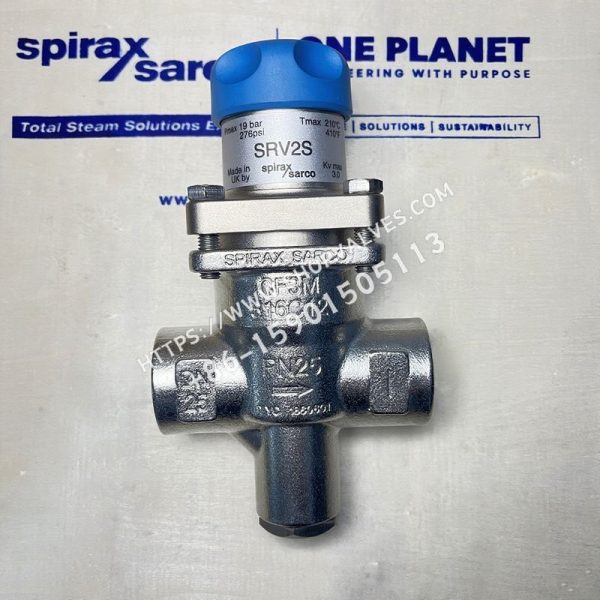
Spirax Sarco SRV2S stainless steel direct-acting pressure reducing valve features a compact design for steam or gas systems, including compressed air. All wetted parts are 316 stainless steel. Three downstream pressure ranges are available and identified by handwheel color markers.
Downstream Pressure Setting Ranges
| Color | Downstream Control Pressure Range |
|---|---|
| Gray | 0.14 - 1.7 bar g |
| Green | 1.40 - 4.0 bar g |
| Orange | 3.50 - 8.6 bar g |
Standards and Certificates
-
The product fully complies with the European Pressure Equipment Directive 97 / 23 / EC and can be supplied with CE marking upon request.
-
An EN10204 3.1 certificate is available. All certificates and tests must be specified when placing the order.
Port Sizes and Pipe Connections
-
½”, ¾” and 1”: BSP (BS 21) or NPT threaded connections.
-
DN15, DN20 and DN25: EN 1092 PN25 and ANSI 150 flanges.
Pressure/Temperature Limits
| Item | Details |
|---|---|
| Valve body design condition | PN25 |
| PMA maximum allowable pressure | 25 bar g @ 120 °C |
| TMA maximum allowable temperature | 212 °C @ 19 bar g |
| Minimum allowable temperature | -10 °C |
| PMO maximum operating pressure for saturated steam | 19 bar g |
| TMO maximum operating temperature | 212 °C @ 19 bar g |
| Minimum operating temperature (consult Spirax Sarco below this temperature) | 0 °C |
| Maximum downstream setting pressure | 8.6 bar g |
| PMX maximum operating differential pressure | 19 bar |
| Recommended maximum pressure reduction ratio (at maximum flow) | 10 : 1 |
| Design maximum cold hydraulic test pressure | 38 bar g (with internal components installed, the test pressure must not exceed 19 bar g) |
Materials
| No. | Component | Material |
|---|---|---|
| 1 | Spring chamber | Aluminum, LM6 electroless nickel-plated surface |
| 2 | Adjusting handwheel | Plastic, polypropylene |
| 3 | Upper spring plate | Cast iron, DIN 1691 GG 20 electroless nickel-plated surface |
| 4 | Pressure adjustment spring | Silicon-chrome spring steel, 2803 685 A55 range 2, electroless nickel-plated surface |
| 5 | Bellows assembly | Stainless steel, 316T/316L |
| 6 | Bellows assembly gasket | Reinforced exfoliated graphite |
| 7 | Spring chamber bolt (M8 × 25mm) | Stainless steel, BS 61.5 A 270 |
| 8 | Valve body | Stainless steel, DIN 1.4404 BS 3100 316 C12 ASTM A351 CF 3M electropolished surface |
| 9 | Guide bearing | PTFE-filled graphite |
| 10 | Top stem | Stainless steel, ASTM A276 316L BS 3100 316 C12 |
| 11 | Valve seat | Stainless steel, ASTM A351 CF3M DIN 1.4404 |
| 12 | Valve seat gasket | Stainless steel, BS 1449 316 S11 |
| 13 | Valve plug | Stainless steel, 316L |
| 14 | Valve plug return spring | Stainless steel, BS 2056 316 S42 |
| 15、16 | Strainer screen | Stainless steel, BS 1446 316 SH |
| 17 | Bottom cover O-ring | PTFE |
| 18 | Spring range color marker | Plastic, polypropylene |
| 19 | Diaphragm | Stainless steel, BS 1449 316 S13 AISI 316L |
| 20 | Pin | Copper-plated mild steel |
| 21 | Flange | Stainless steel, ATNS A315 CF3M electropolished surface |
| 22 | Gasket | Stainless steel, 316L |
| 23 | Threaded push rod | Carbon steel, BS 970 230 M07 electroless nickel-plated surface |
Capacity for Safety Valve Selection
| Port Size | Kvs |
|---|---|
| DN15 | 1.5 |
| DN20 | 2.5 |
| DN25 | 3.0 |
Sizing for Saturated Steam and Compressed Air
Use the sizing chart to select the valve. Numbered curves represent upstream pressure, while the vertical lines on the left represent downstream pressure. The appropriate pressure reducing valve model can be determined according to the required flow rate and pressure.
Weight
| Port Size | Threaded Connection Weight (kg) | Flanged Connection Weight (kg) |
|---|---|---|
| ½” BSP/NPT | 1.48 | - |
| DN15 PN25 | - | 3.1 |
| DN15 ANSI 150 | - | 2.4 |
| ¾” BSP/NPT | 1.58 | - |
| DN20 PN25 | - | 3.8 |
| DN20 ANSI 150 | - | 2.8 |
| 1” BSP/NPT | 1.70 | - |
| DN25 PN25 | - | 4.4 |
| DN25 ANSI 150 | - | 3.6 |
When ordering spare parts, refer to the descriptions in the available spare parts list and specify the pressure reducing valve port size, model and pressure range.
Installation Instructions
Install the pressure reducing valve in a horizontal pipeline, following the flow direction indicated by the arrow on the valve body.
Ordering Information
Example: 1- BSP SRV2S pressure reducing valve, stainless steel bellows, fitted with orange spring (3.5 - 8.6 bar g), ½”.