Description
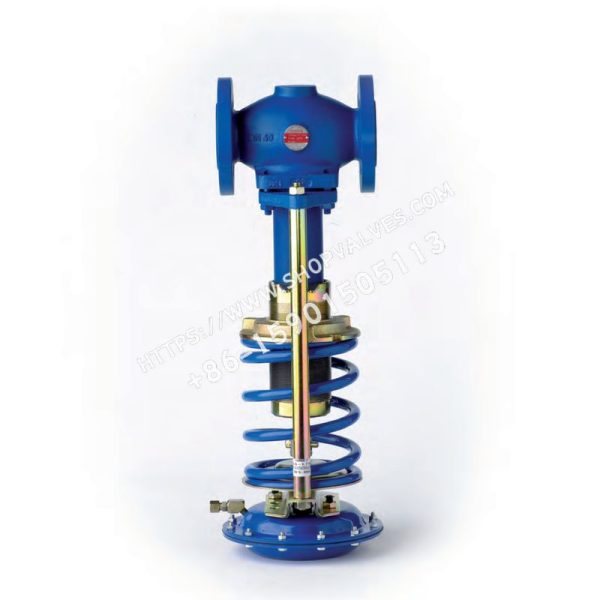
Spirax Sarco DEP4 cast steel overflow valve is a direct-acting, bellows-sealed overflow valve with a cast steel body. The standard model is fitted with an EPDM diaphragm, with a maximum operating temperature of 125°C, and is suitable for water and steam systems. A nitrile rubber diaphragm, identified by suffix “N” and with a maximum operating temperature of 90°C, is also available for oil systems. Note: In steam systems, an upstream WS4 water seal pot must be used to protect the actuator diaphragm. See TI-S12-03 for details.
Standards
The product fully complies with the European Pressure Equipment Directive 97 / 23 / EC and is supplied with the required marking where applicable.
Certificates
As standard, the product is supplied with a manufacturer’s typical test certificate. An EN 10204 3.1 certificate is available on request. Note: Required certificates and testing requirements must be specified when placing the order.
Available Models
Flanged connections from DN15-DN100 are available in 6 pressure ranges, identified by suffixes 1-6.
Upstream Pressure Ranges
| Range | Valve Model | Actuator Model | Spring Color | DN15 - DN40 Pressure Range (bar) | DN50 - DN80 Pressure Range (bar) | DN100 Pressure Range (bar) | PN Rating |
|---|---|---|---|---|---|---|---|
| 1 | DEP4B1 | 11 or 11N | Yellow | 0.1 - 0.5 | 0.1 - 0.3 | 0.1 - 0.3 | 2.5 |
| 2 | DEP4B2 | 12 or 12N | Yellow | 0.2 - 0.8 | 0.2 - 0.5 | 0.2 - 0.5 | 2.5 |
| 3 | DEP4B3 | 13 or 13N | Blue | 0.5 - 1.7 | 0.4 - 1.3 | 0.4 - 1.0 | 6 |
| 4 | DEP4B4 | 14 or 14N | Blue | 1.4 - 3.4 | 1.0 - 2.6 | 0.8 - 2.5 | 16 |
| 5 | DEP4B5 | 15 or 15N | Blue | 3.2 - 7.5 | 2.3 - 5.5 | 2.3 - 5.0 | 25 |
| 6 | DEP4B6 | 15 or 15N | Red | 7.0 - 16.0 | 5.0 - 15.0 | 4.0 - 10.0 | 25 |
Sizes and Pipe Connections
DN15, DN20, DN25, DN32, DN40, DN50, DN65, DN80 and DN100 flanges: EN 1092 PN40. JIS and ANSI 150, ANSI 300 flanges are available on request.
Pressure/Temperature Limits
| Body Design | PN40 |
|---|---|
| PMA Maximum Allowable Pressure | 40 bar g @ 50°C |
| TMA Maximum Allowable Temperature | 300°C @ 25.8 bar g |
| Minimum Design Temperature | 0°C |
| TMO Maximum Operating Temperature with EPDM Diaphragm | 125°C |
| Maximum Operating Temperature with Nitrile Rubber Diaphragm | 90°C |
| Minimum Operating Temperature (Ambient) | 0°C |
| PMX Maximum Operating Differential Pressure | DN15 - DN50 25 bar; DN65 - DN100 20 bar |
| Designed Maximum Cold Hydraulic Test Pressure | 60 bar g |
| Note | After internal components have been installed, the test pressure must not exceed 40 bar g |
Kvs Values
| Nominal Size DN | 15 | 20 | 25 | 32 | 40 | 50 | 65 | 80 | 100 |
|---|---|---|---|---|---|---|---|---|---|
| Kvs | 3.4 | 6.5 | 11.4 | 16.4 | 24 | 40 | 58 | 92 | 145 |
Note: The KVS values above are for the valve fully open and are used for safety valve sizing.
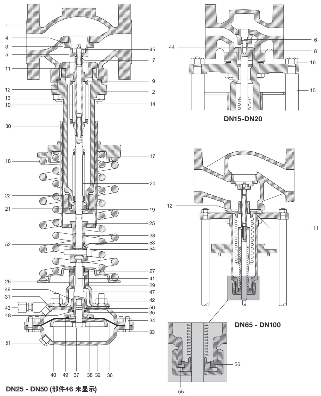
Materials
| No. | Component | Material |
|---|---|---|
| 1 | Valve body | Cast steel GP 240 GH |
| 2 | Bonnet | Cast steel DIN 17245 GSC25 |
| 3 | Valve seat | Stainless steel BS 970 431 S29 |
| 4 | Valve seat gasket | DN15: stainless steel; DN20 and DN25: low-carbon steel; DN32 - DN50: reinforced exfoliated graphite |
| 5 | Valve plug | Stainless steel BS 970 431 S29 |
| 6 | Valve plug bolt | DN15 and DN20: stainless steel BS 6105 A2 |
| 7 | Valve plug seal | DN15 and DN20: Arlon 1555 |
| 8 | Spindle sleeve | Stainless steel BS 970 431 S29 |
| 11 | Balanced bellows assembly gasket | DN25 - DN100: reinforced exfoliated graphite |
| 12 | Bonnet gasket | Reinforced exfoliated graphite |
| 13 | Bonnet bolt | DN15 - DN40 M10: steel DIN 267 Pt13 Gr. 8 |
| 14 | DN50 and DN65 M12: steel DIN 267 Pt13 Gr. 8.8; DN80 and DN100 M16 | |
| 15 | Stud | Galvanized steel BS 970 230 M07 |
| 16 | Stud nut | Galvanized steel BS 3693 Gr. 8 |
| 17 | Spring adjuster | Galvanized cast iron DIN 1691 GG25 |
| 18 | Spring | Chrome vanadium steel |
| 19 | Bearing (part of component 20) | PTFE / steel composite |
| 20 | Sealing bellows assembly | Stainless steel AISI 316L |
| 21 | Sealing bellows gasket | DN15 and DN20: stainless steel ‘S’ type; DN25 - DN100: reinforced exfoliated graphite |
| 22 | Retaining nut | DN25 - DN100: galvanized steel BS 970 230 M07 |
| 25 | Locknut | Galvanized steel BS 970 230 M07 |
| 26 | Spring plate | Galvanized steel BS 1449 Pt 1 HR14 |
| 27 | Needle bearing | Steel |
| 28 | Setting nut | Galvanized steel BS 970 230 M07 |
| 29 | Bearing locator | Galvanized steel BS 970 230 M07 |
| 30 | Adjuster sleeve | Galvanized steel |
| 31 | Mounting plate | Types 11(N) - 14(N): galvanized steel BS 1449 Pt 1 HR14 DIN 1514 St W24 |
| 32 | Housing | Type 15(N): steel BS EN 10025 S355 J2G3 |
| 33 | Housing bolt | Types 11(N) - 12(N): galvanized steel BS 3692 Gr. 5.6; Types 13(N), 14(N) and 15(N): galvanized steel BS 3692 Gr. 8.8 |
| 34 | Housing nut | Types 11(N) and 12(N): galvanized steel BS 3692 Gr. 5.6; Types 13(N), 14(N) and 15(N): galvanized steel BS 3692 Gr. 8 |
| 35 | Top stem guide | Stainless steel BS 970 431 S29 |
| 36 | Diaphragm | EPDM or nitrile rubber |
| 37 | Hexagon screw | Stainless steel BS 6105 A2 |
| 38 | Sealing washer | Fiber |
| 39 | Diaphragm clamp | Stainless steel ASTM A351 CF8M |
| 40 | Piston | Galvanized carbon steel BS 1449 Pt 1 HR14 |
| 41 | Top stem | Galvanized carbon steel BS 970 230 M07 |
| 42 | Mounting nut | Galvanized steel BS 3692 Gr. 8 |
| 43 | Pipe connector | Galvanized steel |
| 44 | Threaded insert | DN15 and DN20: stainless steel DTD 734; DN25 - DN100: galvanized steel BS 1449 CR4 |
| 45 | Self-locking nut | Galvanized steel BS 1449 CR4 |
| 46 | Washer | Type 12(N) only: galvanized steel |
| 47 | Circlip | Galvanized steel |
| 48 | Top stem sealing ‘O’ ring | EPDM or nitrile rubber |
| 49 | Support | PTFE/steel composite |
| 50 | Housing sealing ‘O’ ring | EPDM or nitrile rubber |
| 51 | Drain plug | Plastic |
| 52 | Connecting clamp | Galvanized steel ASTM A216 Gr. WCB |
| 53 | Spring | Spring steel BS 5216 Gr. M4 |
| 54 | Retaining screw | Galvanized steel BS 4168 Gr. 12.9 |
| 55 | Retaining plate | DN65 to DN100 only: stainless steel ASTM A276 316L |
| 56 | Sealing gasket | Reinforced exfoliated graphite |
Sizing for Steam Applications
Use the sizing tables to determine the valve Kv based on upstream pressure, maximum valve pressure drop and maximum steam load. Once the valve Kv is known, the valve pressure drop at any given flow rate can be determined.
Sizing for Water Applications
Use the sizing tables to determine the valve Kv based on maximum flow rate and maximum valve pressure drop. Once the valve Kv is known, the valve pressure drop at any given flow rate can be determined.
Spare Parts
Available Spare Parts (DN15 to DN20)
| Connection Head | A |
|---|---|
| Diaphragm Assembly (Diaphragm and Gasket) | B, C |
| Needle Bearing | D |
| Sealing Bellows Assembly | Sealing bellows, bellows gasket and bonnet gasket: E, F, G, H |
| Control Spring | I |
| Valve Seat/Plug Assembly | Valve seat, valve seat gasket, valve plug and bonnet gasket: J, K, L, G, H |
| Gasket Set | Sealing bellows gasket, bonnet gasket and valve seat gasket: F, G, K |
| Actuator Stem Guide Set | Stem guide, bearing sleeve, stem sealing ‘O’ ring, chamber sealing ‘O’ ring and retaining ring: P, R, S, T, V |
Available Spare Parts (DN25 to DN100)
| Connection Head |
|---|
| Diaphragm Assembly (Diaphragm and Gasket) |
| Needle Bearing |
| Sealing Bellows Assembly |
| Control Spring |
| DN25-DN50 Valve Seat/Plug Assembly |
| DN65-DN100 Valve Plug Assembly |
| DN25-DN50 Balanced Bellows Assembly |
| DN65-DN100 Balanced Bellows Assembly |
| DN25-DN50 Gasket Set |
| DN65-DN100 Gasket Set |
| Actuator Bearing Assembly |
Order spare parts according to the descriptions above, specifying the valve size and model. Example: 1 - gasket set for DN25 DEP4B1 overflow valve.
Installation
For detailed installation instructions, refer to the installation and maintenance guide supplied with the spare parts.
Weights
Valve Weight (kg)
| Valve Size | DN15 | DN20 | DN25 | DN32 | DN40 | DN50 | DN65 | DN80 | DN100 |
|---|---|---|---|---|---|---|---|---|---|
| Yellow Spring Weight | 11.6 | 13.3 | 16.7 | 21.4 | 23.7 | 26.3 | 37.7 | 46.0 | 69.8 |
| Blue Spring Weight | 11.6 | 13.3 | 16.7 | 21.4 | 23.7 | 26.3 | 37.7 | 46.0 | 69.8 |
| Red Spring Weight | 13.6 | 14.8 | 18.2 | 22.9 | 25.2 | 27.8 | 39.4 | 47.7 | 72.5 |
Actuator Weight (kg)
| Actuator Model | 1 or 1N | 2 or 2N | 3 or 3N | 4 or 4N | 5 or 5N |
|---|---|---|---|---|---|
| Weight | 12.3 | 6.5 | 4.0 | 2.6 | 2.7 |
Note: Total product weight equals the combined weight of the valve and actuator.
Safety Information, Installation and Maintenance
For detailed information, refer to the installation and maintenance guide supplied with the product (IM-S12-10).
Note: When used in steam systems, a WS4 water seal pot must be installed upstream and connected to the actuator by an impulse tube to protect the actuator diaphragm. See TI-S12-03 for details. Install the valve vertically downward in a horizontal pipeline, ensuring that the flow direction matches the arrow on the valve body. The valve may also be installed vertically upward when the upstream temperature is below 125°C.
Ordering Information
Example: 1 - Spirax Sarco DN40 DEP4B3 direct-acting overflow valve, flanged connection, PN40. Note: Add suffix ‘N’ when a nitrile rubber diaphragm is required, for example DEP4 B3N.