
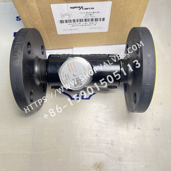
Description
Spirax Sarco TD25 thermodynamic steam traps are designed for low-load steam mains and tracing lines, as well as other applications within their pressure, temperature, and flow limits. Maximum operating pressure is 25bar g.
Available Models
| Model | SKU |
|---|---|
| DN15 TD25 | 1511015001 |
| DN20 TD25 | 1511020001 |
| DN25 TD25 | 1511025001 |
Sizes and Pipe Connections
1/2”, 3/4”,1”BSP or NPT threaded connections. DN15,20 and 25, threaded flange connections EN1092/ISO7005, PN25.
Options
Insulation cover: prevents excessively frequent trap cycling caused by excessive heat loss when the steam trap is exposed to low ambient temperatures, wind, or rain.
Limiting Conditions
| Maximum body design condition | PN40 |
|---|---|
| PMA maximum allowable pressure | 40 bar g |
| TMA maximum allowable temperature | 400°C |
| PMO maximum operating pressure with saturated steam | 25 bar g |
| TMO maximum operating temperature | 400°C |
| Maximum cold hydraulic test pressure | 60 bar g |
Note: Under operating conditions, the maximum operating backpressure must not exceed 80% of the inlet pressure; otherwise, the steam trap will not close.
Materials
| No. | Component | Material |
|---|---|---|
| 1 | Body | Stainless steel ASTM A743 Gr.CA40F |
| 2 | Cap | Stainless steel AISI 416 |
| 3 | Disc | Stainless steel BS 1449420 S45 |
| 4 | Strainer screen | Stainless steel BS 1449 304 S16 |
| 5 | Strainer cap | Stainless steel AISI 416 |
| 6 | Strainer cap gasket | Stainless steel BS 1449 304 S16 |
| 7 | Insulation cap (optional) | Aluminum |
| 8 | Flange | Carbon steel pipe |
Weight
| Size | Flanged weight (kg) | Screwed weight (kg) |
|---|---|---|
| DN15 | 2.4 | 0.75 |
| DN20 | 3.1 | 0.95 |
| DN25 | 4.2 | 1.50 |
Cleaning or Replacing the Strainer Screen
Loosen the strainer cap with a wrench, remove the strainer screen, and clean it. Replace the screen if it is damaged. During reassembly, insert the screen into the cap and screw the cap into the valve body. Apply a small amount of molybdenum disulfide lubricant to the leading threads, ensure that the gasket surface is clean, and tighten the strainer cap to the recommended torque.
Disposal
This product is recyclable and, when disposed of properly, will not cause ecological problems.
Ordering Instructions
Example: 1 - Spirax Sarco 1/2” TD25 thermodynamic steam trap, BSP threaded connection.
Spare Parts
Pressure discs (set of 3), strainer screen and gasket, insulation cover, strainer cap gasket (set of 3)
Installation
The steam trap should preferably be installed in a horizontal pipe with a short length of downward-sloping pipe upstream. Isolation valves must be installed to allow servicing and replacement. A suitable method of checking whether the steam trap is operating correctly should also be provided, such as a sight glass or Spiratec system. The sight glass must be installed at least 1m downstream of a blast-discharge steam trap. When the steam trap discharges into a closed condensate return system, install a check valve downstream to prevent reverse flow. Remove all packaging and protective covers, and ensure that all connections are clean and unobstructed. Slowly open the isolation valve until normal operating conditions are reached to prevent system shock. Check the steam trap for leakage and correct operation. Always use the correct tools, safety procedures, and protective equipment.
If an insulation cover is fitted, remove it first. Then loosen the valve cap with a standard wrench. Do not use an adjustable wrench or pipe wrench, as this may damage the cap. If the disc and seat surfaces show slight wear, use lapping compound and lap the disc and seat separately using a figure-eight motion. If wear is extensive and cannot be corrected by lapping, the seat surface must be machined and polished. Note: a new disc must be installed. Lapping must not remove more than 0.25mm. During reassembly, the grooved side of the disc must contact the seat surface. Tighten the valve cap without using a gasket, but apply a suitable high-temperature anti-seize grease.